Friday, September 19, 2008

Even more curtain wall experiments

I spend a far amount of time travelling each week from where I live in the UK to London. I travel mostly by train as it gives me time to do "stuff" as well as experiment with Revit on my laptop. I often get an idea which I want to try and then it turns into mini design study with many options! Most of them are a load of rubbish to be honest, but it does give me to chance to push Revit to see what can be achieved. Although Revit doesn't provide you with organic tools that products such as 3dsmax, Maya, Rhino and Alias Studio offer, you can still create some interesting forms.

So using the same method described in my previous post, nesting generic families into a cw family, I created these. You will see a common theme as well as how each one was pushed on to create even more complex patterns.

image

image

This is the cw panel family, which consisted of swept blends.

image

This version again consists of swept blends, but in a heliacal form.

image

image

This is the swept blend, driven vertically.

image

image

image

Most of these are a bit out there! But it was fun creating them, I hope they inspire.

Monday, September 08, 2008

Even more Gustav Opus!

I was extremely impressed to see what fellow bloggers Craig @ http://irevit.blogspot.com/ and Dave @ http://do-u-revit.blogspot.com/ had been doing, by utilizing there Revit skills in an attempt to create some of the amazing sculptural patterns that can be found at the Erwin Hauer's website.

Credit goes to Craig Barbieri who kicked this all off!

Hauer_Panel_test_1_closeup_thumb[1]

Credit goes to Dave Baldacchino who is obviously as geeky as me! :-)

Opusplan

The power of curtain walls

I personally find curtain wall systems one of Revit's more powerful features, although it does have some limitations and creating this sort of panel type is not easy. So in a vane attempt to copy what Craig and Dave had achieved, I put my thinking cap on to come up with my interpretation on what they had created. My resulting solution is not as organic as theirs, but it does show what can be achieved with a bit of lateral thinking. This is my answer to the problem...

opus_image1

opus_image2

So how did I create this you may ask? Well, often with this type of panel I find is easier to create it as a generic model family and then nest it into a curtain wall panel family and then load this into a curtain wall system. So I started with a generic model family and setup some additional work planes. Next I created a revolve form, created at the centre of the panel.

opus_image3

Next I added four extrusions to fill in the four corners of the panel and then used the join geometry tool to join these elements to the previously created revolve.

opus_image4

The next stage was to create a void extrusion which would cut the panel to form part of the twist shape you see in the rendered views. The initial shape was sketched out completely using symbolic lines.

opus_image5

This gave me this result, but this only formed the first part of the panel.

opus_image6

I next duplicated the above family and altered the revolved so that it bulged inwards and then altered the void cuts to so that they would complete the figure "8" void you can see in the images.

opus_image7

The resulting two generic families where then loaded into a curtain wall panel family and aligned and locked to the reference planes within the curtain wall panel family. This is especially important as this is where things can go "pear shaped"! This was the panel completed.

opus_image8

All I needed to do next, was to load it into a project, draw a curtain wall and setup the grid parameters of the CW to match the size defined in the panel and then make sure that this new CW system used my new panel type.

opus_image9 

I'm sure there are other ways to create this, however, I hope you find this "enlighting" and it helps you understand that these type of forms can be created within Revit utilizing its current tool set. All I need to do now is work out how to drive the actual curtain wall panel shape using parameters! ;-)

opus_image10

Friday, September 05, 2008

The Revit Clinic

This is well worth a look and I expect it to have some very useful tips as the site develops.

http://revitclinic.typepad.com/

Harlan Brumm is the Global Technical Lead for Revit with Product Support. I've been told that this site will be focusing on all the Revit Products and working to help customers prevent and solve BIM issues.

Thursday, August 28, 2008

IES plugin for Sketchup

IES have released a plugin that allows Sketchup direct access to all the IES tools including the Free VE-ware, VE toolkits as well as the full <Virtual Environment>.

http://www.iesve.com/content/default.asp?page=s156

 ketchup

Interestingly this is compatible with both the free and pro versions of Sketchup. This is obviously an interesting move on IES's part as they are looking to drag the average architect who may not be using a BIM tool forward, by enabling environmental analysis directly from Sketchup. This is great news for the shift towards environmental design, but I doubt it will really concern the Revit user that much and does really help the whole BIM process. Although Sketchup may be good at the concept design, those that have learned to master Revit's massing tools will see more benefit by going direct to IES and cutting out the middle man. But that's just my view.

Displaying your levels at the correct above sea level

This query comes up on a regular basis; How do I display my levels at the correct above sea level? You may be mistaken to think that everything in the world of Revit is flat and new users often get confused by levels, thinking that they should actually move the levels vertically to the correct above sea site level. It is possible to do this, but what if you've started your project and only later do you get the correct survey information. The golden rule is never to move your project, in plan or vertically, I can assure you, Revit does not like this at all. So how do we solve this problem? Well we can setup levels to display the "Elevation base" as shared.

The principle is to move the coordinate system, but not the model, similar to sharing coordinates in plan. So to adjust the default project level of 0m to +16.400m you need to do the following.

Start by going to any elevation view and zooming into level 1 or level 0, depending on how your template defines the first level.
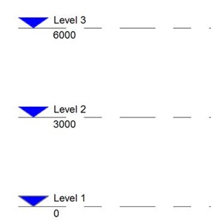
clip_image001

Next go to the tools pulldown menu and select shared coordinates > specify coordinates at a point.
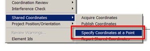
clip_image002

You will discover that you pointer will change to a target. Select your lowest level with the target. This will open up the following dialogue box.
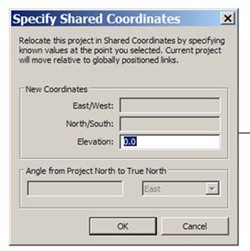
clip_image003

In the elevation field, type in the level you actually require. In this case 16400.
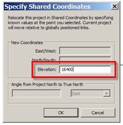
clip_image004

Once you’ve typed the value in, exit out of this dialogue. If you take a look at the levels, nothing seems to have changed. What we actually need to do is to get Revit to display the level as "shared" rather than "project" . To do this select level 1 and go to element properties.
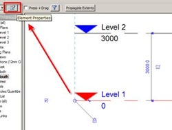
clip_image005

This will open up the element properties window. Click the edit/ new button…..
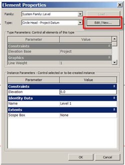
clip_image006

We will now create a new level type, which will allow us to display the elevation base units of shared rather than project. Start by duplicating the default level type and renaming this something like “shared datum”.
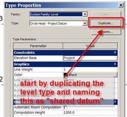
clip_image007

Next we will edit the new level type and change the Elevation Base from “project” to “shared”. Once you’ve done this click “apply” and exit out of the type properties dialogue, then exit out of the element properties dialogue.
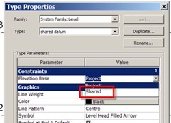
clip_image008

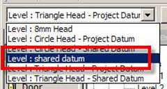
Finally, select all the levels in your elevation view, then go to the type properties drop down menu and select the previously created “shared datum” level type from the type selector.
clip_image010

Your project will now use the Shared datum level type with the elevation base set to “shared” and therefore all your levels will display the correct above seas level. You can easily swap back to the “project” level type by selecting the levels and using the previous level type which had its elevation base set to "project".

clip_image001[4]

Saturday, August 23, 2008

Waterman and Revit Structure

mall_dome_roof_under

A fellow Revit user, Mike Hacker, has setup a rather useful Revit Structure blog which is well worth taking a look at.

http://www.revit-waterman.blogspot.com/

Mike works as a CAD manager for the Waterman Group and is very keen advocate of the Revit technology. You will find some useful tips as well as some great project examples. For those that don't know, the Waterman Group is one of Britain’s premier, multi-disciplinary engineering and environmental consultancies, delivering both small and large-scale projects nationally and internationally.