Friday, December 21, 2007

Merry Christmas and a Happy New Year 2008!!

I would just like to thank everybody who has read my blog during 2007!!! I hope you have found it useful and I look forward to posting more words of wizdom during 2008!

I'd like to wish you all a Merry Christmas and a Happy New Year!!!

Extension for Revit 2008 - "Static analysis of Slabs".

The guys over at Robobat have released a new Extension called the "Static analysis of Slabs". Anyone who went to AU would have seen this new tool demonstarted at the AEC breakfast briefing. The extension can be downloaded from the following location...

http://www.extensions4revit.com/n/e4r/847/53

You will also notice that you will need the update Extension Engine 1.8 to use this tool, which will also mean you need to reinstall all your existing extension!! Thankfully Robobat have seen sense and released the Extensions as a complete package, thank goodness for that!!!

http://www.extensions4revit.com/n/e4r/0/52

Finally, if you have issues installing the latest engine follow this guidance from the Robobat support teams after I discovered a minor bug in the installer.

"When I try to install the new extension engine, the package discovers the old 1.6 engine and asks if I’d like to uninstall the old version first.
If you say “yes”, nothing happens and the installer drops out in the background without warning. If I then go to add remove/programs to try to uninstall the Extensions for Revit v.1.6, the uninstall button does nothing. " To resolve this.

Open registry editor.

Find: HKEY_LOCAL_MACHINE\SOFTWARE\\Microsoft\Windows\CurrentVersion\Uninstall\

Remove {65DC83F9-6B74-4F70-9927-4851AEE116F5} registry

Then run installation of Revit Extensions 1.8.

New Build of Revit Structure has been made avaiable

A new Build of Revit Structure 2008 has been made avaiable for download from the Autodesk website. It has been released to address some issues which 3rd party developer partners had highlighted (beams creation with NewFamilyInstance) in the Revit Structure 2008 previous SP3 build (20071109_2345).

http://usa.autodesk.com/adsk/servlet/index?siteID=123112&id=9262026

The Beam and Beam website suggest that its not worth downloading unless you are using the API tools.

http://bimandbeam.typepad.com/

However, Steve Stafford has reported that it does resolve an issue he highlighted when when using the copy/paste tools applied to concrete beam families.

http://revitoped.blogspot.com/

Wednesday, November 28, 2007

AU2007

AU2007 is in full swing, its bigger and better than last year. With over 10000 attendees worldwide descending on Las Vegas this is the biggest AU ever! The opening technology session this morning was introduced by Lynn Allen with a keynote speech by Autodesk CEO Carl Bass, followed by CTO Jeff Kowalski. The renowned designer Yves BĂ©har presented his vision for value design and showed a number of signature award winning concept design http://www.fuseproject.com/ including the Jawbone headset, xo-1 $100 laptop and LED lamp for Herman Millar. The audience where sat in a circular formation with the central stage with screens position in the middle. The backdrop also consisted of projected screens surrounding the audience. The attendees where teased with possible future Autodesk technologies which where projected onto these screens with high tempo bass driven beats!! It was a visual and audible delight! The audience where also shown a new preview technology product called Newport, which is a rendering and animation tool for the novice user. It was introduced as a tool for the casual user and can be learnt in a lunchtime! It doesn't look like it will replace 3dsmax but it will fill the gap for users who want to do high quality visuals but do not have the time and patients to learn complex products like Viz and Max. This was excellent, but no time frame for this as a usable product was given.


What’s this all to do with Revit you may ask? Well the eagle eyed may have spotted some Revit futures, but it was caveated with the normal Autodesk statement that these are concepts only. :-) Hmmmm lets see what 2009 release has to bring. However, what was shown at the AEC technology breakfast was a new Extension4 Revit Structure which allowed you to do analysis directly within Revit Structure. Time frame was not given and this was the first time it has ever been demonstrated.


Mastering Revit Architecture 2008 (Mastering) book


Want a technical in depth book on Revit Architecture 2008? Then you need the new Mastering Revit Architecture 2008 which has just been published. The book is the second in the series from Tatjana Dzambazova, Eddy Krygiel and Greg Demchak and builds on the Revit principles defined in there first book Introducing Revit Architecture 2008. The first book was excellent and from what I'm hearing the second is just as good. It can be found on Amazon, but if you are attending AU2007 in Las Vegas this year be sure to drop by the exhibition hall as you will be able to get a copy there. If you are really lucky and are attending AU, then I’m sure if you see Tatjana she will sign a copy for you! ;-)

Wednesday, November 21, 2007

IES plugin for Revit Architecture

IES have just annouced a free plug-in to Revit Architecture which provides a direct link to their software. This now provides Architecture with similar and enhanced fuctionality as you find in Revit MEP. Details can be found at:-

http://www.iesve.com/content/default.asp?page=s62&newsid=1924&back=home

Tutorials and functionality can be found here:-

http://www.iesve.com/content/default.asp?page=s97

Tuesday, November 20, 2007

Importing 3d DWG’s into Revit

I had an interesting situation recently where an experienced Revit user questioned whether you could bring a 3d DWG into Revit????!!!! This was somewhat of a surprise to me, because I just assumed that most users will know that this is possible. However, I suppose the real question is what value does this bring and in what context would you want to use the 3d DWG. In reality the 3d DWG is only contextual background data, but if you are clever you can bring a 3d DWG into a mass family. Then, if you load your mass family into your project you can use Revit’s building maker functionality to skin the 3d DWG with Revit’s system families ie. walls, roofs and curtain walls. You will quickly be able to create something which is usable. A point to note is ideally if you are importing into a mass family, the 3d DWG must be made up of AutoCAD solids. The first link shows you how to link a 3d DWG in a project, the second link shows you how to import a 3d DWG into a mass family.

Friday, November 16, 2007

New Builds of Revit 2008 portfolio available

Autodesk have just released new builds (20071109_2345) of Revit Architecture, Revit Structure and Revit MEP (service pack 3). Details can be found at the following locations:-

Revit Architecture
http://usa.autodesk.com/adsk/servlet/index?siteID=123112&id=9262388

Revit Structure
http://usa.autodesk.com/adsk/servlet/index?siteID=123112&id=9339705

Revit MEP
http://usa.autodesk.com/adsk/servlet/index?siteID=123112&id=9262907

A pdf is available for download on each page indicating what has been addressed in this service pack.

AUGI Design Academy, Birmingham, UK 13th to 14th Nov

I have just returned from the first ever AUGI Design Academy user event which was held in Birmingham, UK on the 13th and 14th Nov. This was the first time anything like this has ever been held in the UK. I was fortunate enough to be asked to present at the event and I covered two classes; one on using Extreme Architecture using Revit and Inventor together and second class was on BIM collaboration with the Revit portfolio.

It was great to see a number of our US colleagues make there way over especially as this event was so close to AU2007; with the likes of Matt Murphy, Lynn Allen and Phil Read all presenting. You will find more details on Lynn Allens blog.

http://lynn.blogs.com/lynn_allens_blog/2007/11/an-autocad-hip-.html

Although the numbers for this event where small (around 200+), the quality of the presentations was excellent and the feedback from those who attended was extremely positive. I expect to see this event rapidly grow in size next year.

Avatech releases Revit Architecture 2008 tools

Following on from there release of a Google Earth plugin last year, Avatech solutions have released a series of tools specifically for Revit Architecture 2008. Theses include:-

  • A room renumber tool
  • Change font case
  • Door Mark update
  • A Revitcity.com content browser
  • Earth Connector for Revit
These tools are all free for download and can be downloaded from :-


The room renumber is particularly useful!!! Any one who is had a renumber rooms for a large floor plan will love this tool. :-)
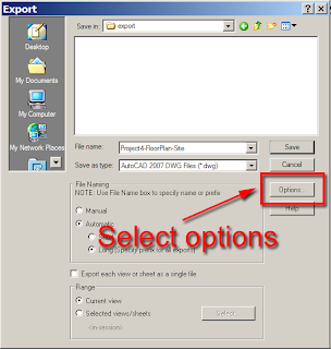
It's great to see this type of development being done for Revit Architecture. With all the focus being on the extension4revit tools for Revit Structure, I am sure users of Revit Architecture had felt like second class citizens.

Friday, September 28, 2007

Revit on the Mac

This is often a hot topic on the Revit AUGI forums and it some times gets very heated! Whats better, Mac or PC? Well, I've been a long term Mac user as well as a Windows PC user. My first computer was a Macintosh LCII, if anybody can remember one of those? I've worked for companies which have used both platforms. I personally love the Mac environment, but I have learned to get on with PC's and the Windows platform. These days I don’t got too bothered about the platform wars, because to me its just an interface to your hardware, Revit as a BIM platform excites me more.

I meet a lot of architects and designers in my role and I have lost count how many have asked whether Revit runs on the Mac. A lot of architects still use Mac's, its just one of those design things. I live near Winchester, Hampshire,UK and this is a strong hold for architectural firms. I'd go as far as to say that over half of these are Mac users running Vectorworks. I'd love to see Autodesk port Revit to the Mac, but commercially I don’t think its viable, well that’s what Autodesk insiders have told me in the past.

However, the landscape has now changed and it all comes down to the fact that all current Apple hardware are based on Intel processors rather than the aging PowerPC. If anybody attended AU last year they will have noticed that Phil Read of Autodesk Consulting fame presented his Advanced Revit session on a Macbook Pro using Bootcamp, which allows him to boot between Mac OS X and Windows, so that he can run Revit on his Macbook.

Also, a company called Parallels Inc introduced virtualization software last year which allows you to run Mac OS X and Windows side by side. What is interesting is that the latest version of Parrallels has DirectX and OpenGL support, even going as far as saying on their website that Revit Architecture 2008 has been tested and works. I haven’t tried it myself, but I know a number of architects as well as Engineers who are working with Parrallels on a Mac and are more than happy with the performance.

http://www.parallels.com/en/products/desktop/features/3d/

If you need to know more, its worth reading this article on Aecbytes from Scott Onstott as he has recently migrated from Windows to using Parrallels on a Mac Book Pro.

http://www.aecbytes.com/tipsandtricks/2007/issue22-WinonMac.html

So in summary, Revit will work on a Mac!! With that in mind, I know my next laptop will be a Macbook Pro. :-)

Friday, September 21, 2007

BIM Wars!!!

If you ever had any doubt about Revit takeup and adoption its worth reading this artcile......

“BIM allows you to be an architect,” says principal Stephen Wright. “The programs are intuitive enough to take a back seat and let the architecture shine through.”
Revit takes command
2000 Revit launches
2006 Revit hits 100,000 seats
2007 Revit hits 200,000 seats


Exporting HSL/RGB colours from Revit to AutoCAD

I have come up against this issue a couple of times recently, so I thought it was worth explaining.

The question is; How can I predict which HSL/RGB colours will export from Revit to AutoCAD correctly, especially when I have created colour fills for my floor plans?

In reality it’s not a predication! At present Revit is limited to the standard 255 ACI colours when exporting to AutoCAD, this is a limitation of the DWG export. Therefore, you will need to make sure that the RGB colours you are using in Revit, match the ACI colours of AutoCAD so that you get a 1 to 1 translation. For instance white in ACI has a hexadecimal value of FF FF FF, which is colour 255 in AutoCAD or an RGB colour of 255,255,255. This webpage http://www.xanadu.cz/ftp.asp has smart utility for download called ACAD COLOR RGB-ACI CONVERTOR (EXE). If you plug in the AutoCAD ACI numbers you will be able to get the equivalent RGB value, this avoids fighting your way through the AutoCAD colour dialogue box. If you then set up the RGB values in Revit to match the same ACI numbers, you will get the output you are looking for.

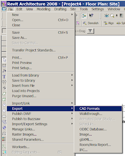
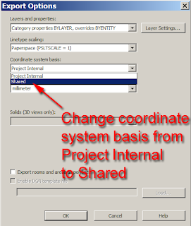
When you do export from Revit to DWG, also make sure that you enable the following setting into the DWG options; this will ensure that the colours get translated correctly.


This will work fine, the room colour fills will export correctly back to DWG, but if your view includes a colour fill legend, this ends up screwy as it fails to export the colours correctly, as the colours in the colour scheme legend do not match the room colours, lets hope Autodesk are aware of this!

The image below shows the resulting colour fills exported from Autocad and overlaid on top of the Revit colour fills. You will notice a few shades are slightly out, but on the whole its correct.

One other point to watch is that although the colours fills will match correctly, in some instances when you open the exported DWG, some colours will not always display a ACI colour number, they actually pickup the RGB value….which is strange. Anyway, I have been sad enough to go through all 255 ACI colours and set these up in Revit, You can download the file from here, that way you can try it your self. :-)

Tuesday, September 11, 2007

New Build of Revit MEP 2008 has been posted

Following on from the recent updates of Revti Architecture and Structure, there is now a new build of Revit MEP 2008 posted. It can be downloaded from here. There are a number of important PDF's file which are worth downloading and ready. The fixes include the following:-

Room Tags on Copy/Monitored Rooms no longer return question marks in certain situations.
Improves stability when using the Split Tool on Pipes or Ducts.
Multiple Sprinkler Systems can now be copied more consistently.
Improves stability when modifying the shape of an Elbow with an open end.
The length override for Duct Transitions remains consistent after changes to the connected layout.
Improves stability when generating ductwork from a mirrored air system.
Improves stability when demolishing a duct with two connected takeoffs.
Improves stability after receiving a corrupt element warning when opening a project.
Publish to DWF™ functions when Rooms are present and are clipped by the viewport.
Improves stability when saving a Project with a linked DWG™ file that contains an image.
Improves stability when applying a view template to a sheet view.
Working on Windows Vista™ operating system, allows the ability to write to revit.ini, licpath.lic, KeyboardShortcuts.txt, and the Journals folder.
Line-based families contained in a group are no longer flipped when the group is mirrored.
Improves stability when importing group into Titleblock family.
Allows the ability to export renderings to TIFF format.
When temporary dimension text too small to read, user can adjust the size of the font through Revit.ini.
Linked DWG file added by another user will now show up in Manage Links after reload latest.
“Relative” spot elevation updates automatically with the change in Level elevation.
When exporting to DWG file, overlapping lines that share a point are no longer missing in the resulting DWG.

Thursday, September 06, 2007

Shared coordinates, true north, project north

Shared coordinates, true north and project north are often a mystery to new users. In reality it’s a straight forward process, but as you only every do it once at the start of a project it is often forgotten by the time you come to implement it on a new project!!!

In principle the process of shared coordinates allows you to import a AutoCAD DWG survey into your Revit project and acquire the coordinates from the imported DWG so that the Revit coordinate system aligns with the DWG coordinates.

There have been many articles on the subject on various blogs as well as AUGI.
However, I will step you through the process I follow, pickup a few issues and hopefully it will be of some help, as well as a useful reminder when you come to implement it on your next project.

I used to work for a firm of architects and before that a housing developer. I was the person tasked with providing setting out drawings for the contractor. So I have fair amount of experience in this process in an AutoCAD environment. In all the buildings I ever provided digital setting out data for, everyone was spot on, so when I started using Revit 5 years ago I was keen to understand how it was working in a Revit environment. There are a number of different approaches for setting up coordinates in Revit, but we are going to focus on the shared coordinate method because often the start point of any project is an AutoCAD DWG survey.

Start Revit in the normal fashion and go to Level 1. Firstly we will import/link our AutoCAD dwg survey. Always link rather than import; make sure you have the right units set and link the DWG survey centre to centre.


The auto-detect process should be ok, but I have lost track of how many people actual draw in AutoCAD without setting the units. If you are an old school AutoCAD users ( remember version 11 DOS, yes I’m showing age), well one of the first things you did was set you units and environment variables.

You should have something which looks like this.

Next we will align the Revit coordinates with the imported AutoCAD coordinates. However, as a check I always place a reference line on one of the known coordinate’s locations on the DWG. Add a reference plan and snap it to the end of one of the known station points in the linked DWG. You should have something like this,


Next from the drafting design bar, select the spot dimension and place a spot coordinate at the end of the reference line. I use this as sanity check when sharing the coordinates.


To align the Revit coordinate system with the imported survey data, go to the tools pull down menu, then shared coordinates, then acquire coordinates; you do this by selecting the imported DWG.


When you select the DWG, it will highlight grey, but to be honest there is no warning of dialogue box which appears to tell you that you have completed this process. But if you check back at the coordinate you created early it will now have changed to match the AutoCAD coordinates, so this is your check.

Now here’s the confusing part. Revit will only recognise the AutoCAD WCS (world coordinate system) so your AutoCAD DWG survey needs to be positioned in relationship with 0,0 in AutoCAD. But there is another problem, if you read the following article on AUGI it will explain, that if your survey is positioned further that 1.7km from 0,0 the shared coordinates process will fail. Having discovered this from my own painful experience my advice would be to make sure your survey is within this zone, then the shared coordinates process will work. If you refer to the image below it should make sense.

Now you’re probably asking, well what the hell do I do if my survey is further out from this?? Well in most cases in the UK the surveyor will often create an arbitrary grid based on the Ordinate Survey grid. He will place a station pin on site and set out a site grid from this. Sometimes it follows the national grid system, other times its an arbitrary grid of his own. Each surveyor seems to have a slightly different approach. Therefore, the best option is to move the DWG survey closer to 0,0. As long as you have a suitable station point on site to refer to it should not be a problem. I can’t confirm what the process is in the US or in other countries, but normally the site location should not be moved, but doing this process allows you to then provide a often dimension to the main station point.

Generally when working in Revit you are working in Project north which is perpendicular to the screen. However, your building and site may be slightly rotated in relationship to true north. So we have tools in Revit which allows us to control project north and true north.

So next we need to rotate the site to true north, so that if we want to set the building out onsite the coordinates work in relationship with the survey data whilst the project plan views remains orthogonal.

Go to site view, then right mouse click and choose view properties and change orientation from project north to true north.


Finally we need to rotate the site so that the building can be worked on orthogonally in the project north views. This is the most confusing part, because you are actually rotating the view and not the plan.

So go to the tools pull down menu, then project position/orientation, then rotate true north. If your building position on the site is at an angle, you need to rotate the view to the angle difference to horizontal.

I have provided two images which show the direction you need to rotate the view depending how the building is position to the horizontal.

You will notice no change in the site view apart from the elevation markers will have rotated, however if you go to any other plan view you will see that the imported dwg is now rotated so you can now start to work on the building orthogonally.
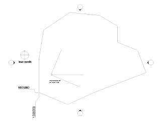
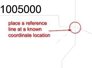
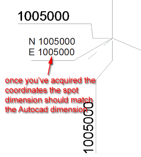
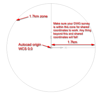
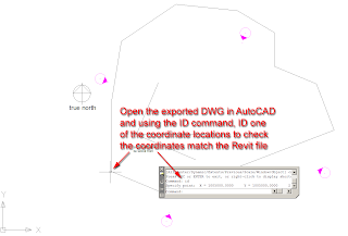
Finally, when you save your project, Revit will ask to write back information to the linked DWG survey, so that the relative positions can be maintained. Make sure you don’t have the DWG open in the background in AutoCAD else the save process will fail!

OK, you’ve completed the exercise. A couple of extra points which often help. Use the pin tool to pin the DWG in place. If you move the DWG in your project you will screw with the shared coordinate system and it can be a nighmare to re-correct it! If you are using workset, create a separate workset for your linked DWG data, this way you can load it and unload it when its note required.

As a final check , I will explain how you can check that everything is working by exporting your site view back to DWG.

Go to the project browser and select site view. Next go to the file pulldown menu, export CAD/formats and select a suitable DWG format.

Click the options button and change the Coordinates System basis from Project Interal to Shared. Ok out of this dialogue and click export to save your DWG to a suitable location.


Open up AutoCAD and then open up your exported DWG. Using the ID command, ID a suitable coordinate or station point on in the DWG to make sure the coordinates are correct. Hopefully everything will be correct!!! Now you can be confident that when you need to export to AutoCAD the building is correct in AutoCAD as well as the Revit world.

Hopefully this has been useful. If you’d like to see a movie example of the above process click this link. Good luck and happy site setting out.

Monday, September 03, 2007

Revit and IES

Anyone who has Revit MEP 2008 will discover that they have IES integrated into the product to allow you to create heating and cooling loads directly from your model. You will also find a link in the heating and cooling loads dialogue box which allows you to convert your BIM model into IES virtual environment. More details and AVI's can be found out at

http://www.iesve.com/content/default.asp?page=s98

http://www.iesve.com/content/default.asp?page=s12

This PDF link will provide you details on what is included within the Sustainability toolkit.

http://www.iesve.com/content/mediaassets/pdf/Sustainability%20Toolkit%20Features.PDF

Broutek - Revit MEP UK content

If you are using Revit MEP in the UK, you may be aware that it lacks UK content, which to some extent is holding up adoption. Along comes a company called Broutek.

http://www.broutek.com/

Broutek have been setup to solve the UK content issue. Take a look at what they have done todate, by going to their website, it all looks very positive. This is from their website.

"We create specific families of M&E parts for the UK’s construction industry.
Our Intelligent BIM Parts are 3D models of equipment and fittings with data
about themselves and knowledge about the systems and environments of
which they are part."

Revitup South Africa


This site is worth a good look.

It has been setup by Justin Taylor who used to work for a large UK reseller and before that Autodesk UK. Justin moved from the UK to South Africa last year and is now working as a technical consultant for a reseller called Modena, http://www.modena.co.za/, which is based in Santon near Johannesburg. He has setup this site to push the merits of Revit for the South African market place. Drop by his site as it has some interesting thoughts and articles on Revit which are worth a look.

Wednesday, August 22, 2007

New Build of Revit Structure 2008 is released

Not to be out done by the architectural team, the structural boys also have a new build posted (20070810_1700). This includes the following inprovements:-

• Straight beam joins and cuts back properly when supported by vertical curved beams.
• Improves stability after receiving a corrupt element warning when opening a project.
• Improves stability when saving a Project with a linked DWG™ file that contains an image.
• Improves stability when applying a view template to a sheet view.
• In Windows Vista™ operating system, allows the ability to write to revit.ini, licpath.lic,
KeyboardShortcuts.txt, and the Journals folder.
• Line based families contained in a group are no longer flipped when the group is mirrored.
• Improves stability when importing group into Titleblock family.
• Allows the ability to export renderings to TIFF format.
• When temporary dimension text too small to read, user can adjust the size of the font through Revit.ini.
• Linked DWG added by another user will now show up in Manage Links after reload latest.
• “Relative” spot elevation updates automatically with the change in Level elevation.
• When exporting to DWG file, overlapping lines that share a point are no longer missing in the resulting
DWG.

The build can be downloaded from:-
http://usa.autodesk.com/adsk/servlet/index?siteID=123112&id=9262026

New Build of Revit Architecture 2008 is released

Autodesk have today released a new build of Revit Architecture, SP2 build (20070810_1700). It includes the following fixes and minor improvements.

• Improves stability after receiving a corrupt element warning when opening a project.
• Publish to DWF™ functions when Rooms are present and are clipped by the viewport.
• Improves stability when saving a Project with a linked DWG™ file that contains an image.
• Improves stability when applying a view template to a sheet view.
• In Windows Vista™ operating system, allows the ability to write to revit.ini, licpath.lic,
KeyboardShortcuts.txt, and the Journals folder.
• Line based families contained in a group are no longer flipped when the group is mirrored.
• Improves stability when importing group into Titleblock family.
• Allows the ability to export renderings to TIFF format.
• When temporary dimension text too small to read, user can adjust the size of the font through Revit.ini.
• Linked DWG added by another user will now show up in Manage Links after reload latest.
• “Relative” spot elevation updates automatically with the change in Level elevation.
• When exporting to DWG, overlapping lines that share a point are no longer missing in the resulting DWG
file.

The build can be downloaded from:-
http://usa.autodesk.com/adsk/servlet/index?siteID=123112&id=9262388

Monday, August 20, 2007

Custom Curtain Wall Panels

Autodesk Revit's Curtain Walls on the face of it, look reasonably basic, but with a bit of lateral thinking you can create extremely complex systems.

Recently I had a request from one of the clients I work with, who required a bespoke curtain wall system. He wanted to create curtain wall system which was more like a glass rain screen cladding system. The curtain wall would actually be hung off the side of the building, but what the client actually wanted to show was that each panel in the system had a 100mm gap between each panel when viewed in elevation. Therefore it was more decorative rather than a weather proof panel system. This is straight forward to achieve using a custom curtain wall panel family in a curtain wall system. This tutorial will hopefully introduce you to the basics of creating custom curtain wall systems.

Start Revit; then go to file>new> family and choose Metric Curtain Wall panel.rft (imperial version if you are in the US). This will open up a new default curtain wall panel family in the family editor. If you haven’t done any family editing before, don’t worry, because this exercise will step you through everything you require.

Family templates are hardwired templates for different elements within Revit. Families are the back bone of Revit, if you are going to create a new door family, you pick the door template. If you want to create a window family, then pick a window template and so on. Autodesk have included a number of pre-set parameters in each template to help you along. However, I digress, returning to our new curtain wall panel family, go to an Exterior elevation.

You will notice 4 reference planes, to horizontal, two vertical. These are the bones of the family. If you where to build a panel in the normal fashion the geometry would need to be locked to these reference panels. However our system needs a 100mm gap between adjacent panels. So go to Ref plane tool in the design bar, then using the pick tool set an offset of 50mm and create 4 additional ref planes placed on the inner side of the main reference planes in the family. You should end up with something like this……

Next using the linear dimension tool, create a dimension between the main reference plan and the reference plan you have just created.

You should end up with this….

Next select one of the dimensions. When you select the dimension the label tool will appear in the options bar. Select the drop down menu which appears and then select Add parameter.

The Parameter properties dialogue box will appear. Give your new parameter a suitable name, I have called mine “offset”. Group the parameter under “dimensions” and set the parameter as a type parameter. Then select the OK button.

The dimension will now convert to a parameter and will display like this.
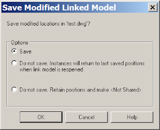
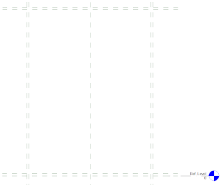
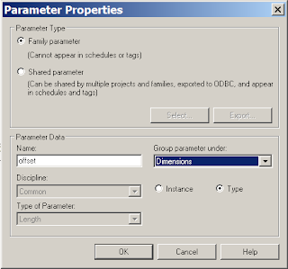
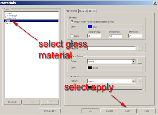
Next we will now flex the parameter to see if it is working correctly. In the design bar select “family type”.
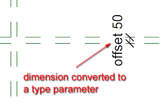
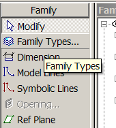
This will open up the family type dialogue box. Locate the parameter you have just assigned and changing the parameter dimension from 50mm to 100mm and click “apply”, this will flex the dimension. Assuming everything is working correctly, return the parameter to 50mm and exit out of the dialogue box.

Next select the other 3 dimensions and assign the offset parameter to each dimension. To do this, select the dimension and select “offset” from the label drop down menu in the options bar.

Now we have created the bones of the curtain wall panel, we will now model the actual glass panel. From the design bar go to solid form > solid extrusion.
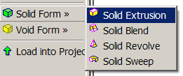
The design bar will change to sketch mode for the extrusion. From the options bar, set the extrusion depth to 35mm for the thickness for the glass.
Now use the pick line tool to place lines for the extrusion on the reference lines you created earlier. However, as you place each line, a pad lock will appear, make sure you lock the pad lock. This will lock the extrusion line to the reference plane.
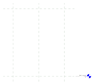
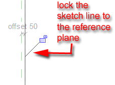
Continue placing reference lines until you have something like this.
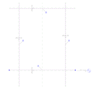
Now use the trim tool to trim the sketch lines until you have a nice clear rectangle.
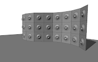
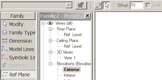
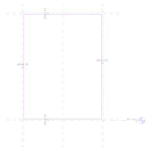
Now select finish sketch from the design bar. Go to the default 3d view icon, to view you panel in 3d.

Select the panel, right mouse click and from the contextual menu select element properties.
The element properties dialogue box will appear. Next select materials, the materials dialogue box will appear, select glass material, click the “apply” button and “ok” out of the dialogue box.
Your 3d panel will now have a glass material applied to it.

We will now save our panel to a suitable location on the hard drive.

Assuming you started Revit from scratch, you should have a project already started and running in the background. If this is the case, you can load your new panel directly into the project by clicking “load into projects”.
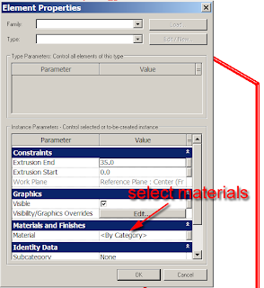
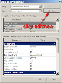
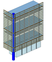
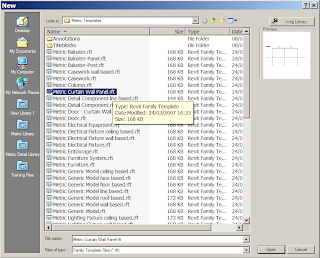
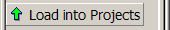
Revit should switch you over to your project.

Now select walls and Curtain wall: exterior glazing (if you are using the metric template). Before drawing a piece of curtain wall, go to the element properties for the curtain wall.
Click edit/new from the dialogue box.


In the Type properties set the following values.

Construction
Make the curtain panel:- custom panel ( your new panel you have just created)

Vertical Grid Pattern
Layout:-Fixed Distance
Spacing:- 2000mm (6’ 6”)

Horizontal Grid Pattern
Layout:-Fixed Distance
Spacing:- 2000mm (6’ 6”)

Select apply and exit out of the dialogue boxes. You are now ready to draw your new curtain wall with the panel embedded into it. Draw the wall in the normal fashion. You may get an error if Revit can’t actually form a panel depending on the length of the curtain wall you are drawing. If you have followed my guidelines correctly and you draw your wall 12m long, then the 2m panel will fit in without any issues.

It’s worth going back to the type properties and playing with the figures as well as Layout conditions to set the different results that can be achieved. If you want to see a movie of the above example, select this link. I hope you find this is helpful. I will introduce some more advanced tricks and tips for Curtain Walls in future postings, but this should be enough to get your juices flowing.