In principle the process of shared coordinates allows you to import a AutoCAD DWG survey into your Revit project and acquire the coordinates from the imported DWG so that the Revit coordinate system aligns with the DWG coordinates.
There have been many articles on the subject on various blogs as well as AUGI.
However, I will step you through the process I follow, pickup a few issues and hopefully it will be of some help, as well as a useful reminder when you come to implement it on your next project.
I used to work for a firm of architects and before that a housing developer. I was the person tasked with providing setting out drawings for the contractor. So I have fair amount of experience in this process in an AutoCAD environment. In all the buildings I ever provided digital setting out data for, everyone was spot on, so when I started using Revit 5 years ago I was keen to understand how it was working in a Revit environment. There are a number of different approaches for setting up coordinates in Revit, but we are going to focus on the shared coordinate method because often the start point of any project is an AutoCAD DWG survey.
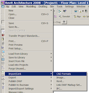
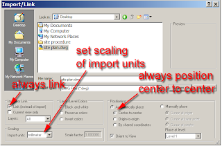
Start Revit in the normal fashion and go to Level 1. Firstly we will import/link our AutoCAD dwg survey. Always link rather than import; make sure you have the right units set and link the DWG survey centre to centre.
The auto-detect process should be ok, but I have lost track of how many people actual draw in AutoCAD without setting the units. If you are an old school AutoCAD users ( remember version 11 DOS, yes I’m showing age), well one of the first things you did was set you units and environment variables.
You should have something which looks like this.
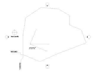
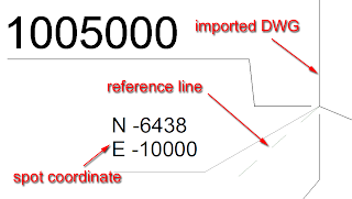
Next we will align the Revit coordinates with the imported AutoCAD coordinates. However, as a check I always place a reference line on one of the known coordinate’s locations on the DWG. Add a reference plan and snap it to the end of one of the known station points in the linked DWG. You should have something like this,
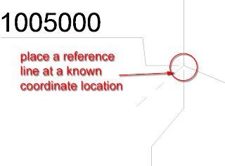
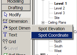
Next from the drafting design bar, select the spot dimension and place a spot coordinate at the end of the reference line. I use this as sanity check when sharing the coordinates.
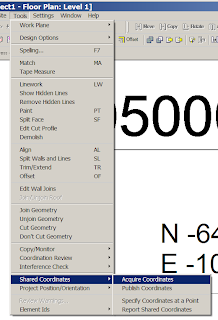
To align the Revit coordinate system with the imported survey data, go to the tools pull down menu, then shared coordinates, then acquire coordinates; you do this by selecting the imported DWG.
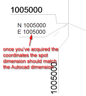
When you select the DWG, it will highlight grey, but to be honest there is no warning of dialogue box which appears to tell you that you have completed this process. But if you check back at the coordinate you created early it will now have changed to match the AutoCAD coordinates, so this is your check.
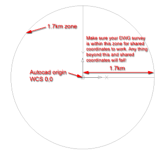
Now here’s the confusing part. Revit will only recognise the AutoCAD WCS (world coordinate system) so your AutoCAD DWG survey needs to be positioned in relationship with 0,0 in AutoCAD. But there is another problem, if you read the following article on AUGI it will explain, that if your survey is positioned further that 1.7km from 0,0 the shared coordinates process will fail. Having discovered this from my own painful experience my advice would be to make sure your survey is within this zone, then the shared coordinates process will work. If you refer to the image below it should make sense.
Now you’re probably asking, well what the hell do I do if my survey is further out from this?? Well in most cases in the UK the surveyor will often create an arbitrary grid based on the Ordinate Survey grid. He will place a station pin on site and set out a site grid from this. Sometimes it follows the national grid system, other times its an arbitrary grid of his own. Each surveyor seems to have a slightly different approach. Therefore, the best option is to move the DWG survey closer to 0,0. As long as you have a suitable station point on site to refer to it should not be a problem. I can’t confirm what the process is in the US or in other countries, but normally the site location should not be moved, but doing this process allows you to then provide a often dimension to the main station point.
Generally when working in Revit you are working in Project north which is perpendicular to the screen. However, your building and site may be slightly rotated in relationship to true north. So we have tools in Revit which allows us to control project north and true north.
So next we need to rotate the site to true north, so that if we want to set the building out onsite the coordinates work in relationship with the survey data whilst the project plan views remains orthogonal.
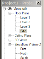
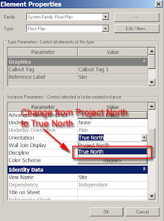
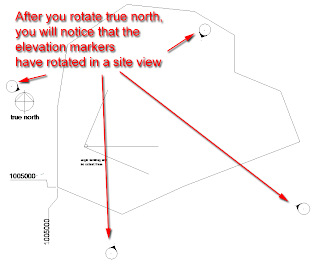
Go to site view, then right mouse click and choose view properties and change orientation from project north to true north.
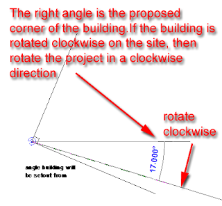
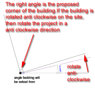
Finally we need to rotate the site so that the building can be worked on orthogonally in the project north views. This is the most confusing part, because you are actually rotating the view and not the plan.
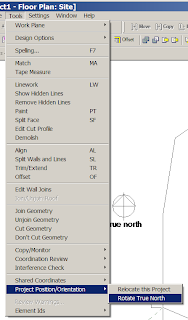
So go to the tools pull down menu, then project position/orientation, then rotate true north. If your building position on the site is at an angle, you need to rotate the view to the angle difference to horizontal.
I have provided two images which show the direction you need to rotate the view depending how the building is position to the horizontal.
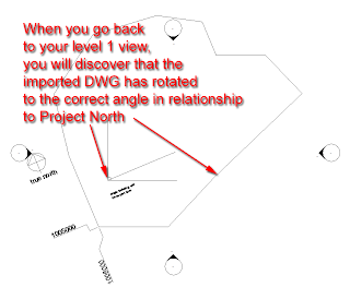
You will notice no change in the site view apart from the elevation markers will have rotated, however if you go to any other plan view you will see that the imported dwg is now rotated so you can now start to work on the building orthogonally.
 Finally, when you save your project, Revit will ask to write back information to the linked DWG survey, so that the relative positions can be maintained. Make sure you don’t have the DWG open in the background in AutoCAD else the save process will fail!
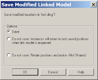
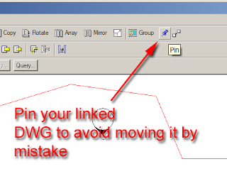
OK, you’ve completed the exercise. A couple of extra points which often help. Use the pin tool to pin the DWG in place. If you move the DWG in your project you will screw with the shared coordinate system and it can be a nighmare to re-correct it! If you are using workset, create a separate workset for your linked DWG data, this way you can load it and unload it when its note required.
As a final check , I will explain how you can check that everything is working by exporting your site view back to DWG.
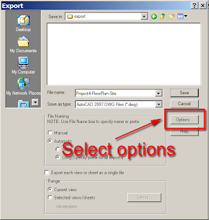
Go to the project browser and select site view. Next go to the file pulldown menu, export CAD/formats and select a suitable DWG format.
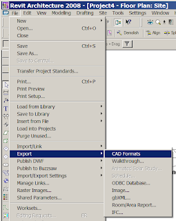
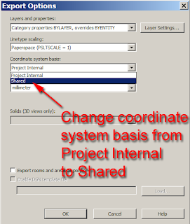
Click the options button and change the Coordinates System basis from Project Interal to Shared. Ok out of this dialogue and click export to save your DWG to a suitable location.
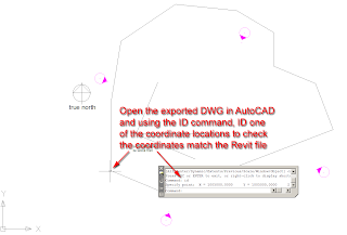
Open up AutoCAD and then open up your exported DWG. Using the ID command, ID a suitable coordinate or station point on in the DWG to make sure the coordinates are correct. Hopefully everything will be correct!!! Now you can be confident that when you need to export to AutoCAD the building is correct in AutoCAD as well as the Revit world.
Hopefully this has been useful. If you’d like to see a movie example of the above process click this link. Good luck and happy site setting out.
13 comments :
In the case where the survey is more than 1.7km away, you mentioned that the survey be moved. Don't you need to 'publish' these new coordinates to the dwg? Reason being, in future, when you get a new survey and reload it, how does your revit project remember where you moved it originally?
Thanks
In the case where the survey is more than 1.7km away, you mentioned that the survey be moved. Don't you need to 'publish' these new coordinates to the dwg? Reason being, in future, when you get a new survey and reload it, how does your revit project remember where you moved it originally?
The second survey drawing will need to be relocated in a DWG environment so that it matches the same origin as the original linked DWG survey. I would always use survey reference stations to do this. All you do then is import link the new survey, but this time rather than bringing it in centre to centre, use shared coordinates instead. When you save the project, Revit will automatically write back a place holder to the second survey, thus it knows where to be located. Finally, if you require, you can remove the original DWG from the project by going to managed links.
David,
Most of the surveys we get are much further than 1.7km away! Our latest is 18 miles.
Is there some sort of script or automated process you can think of to run in the ACAD drawing for making this process viable?
One thought was changing the INSBASE command, but Revit doesn't seem to recognize that.
Thoughts?
Thanks,
Angelo
Hi. I'm drawing my first revit project. As you advised I moved dwg in the 1,7km radius circle. What about z axis? I want to relocate building model at real level. I mean ground floor (0.00) must be at +900m accourding to dwg. Do you think it will be trouble? (2nd alternative moving dwg, but I prefer moving building. because we generally define elevations according to municipality's level for formal submission.
The z height seems to be less of an issue. I would never move the dwg in a z direction instead do the following. In a elevation view, go to tools menu>project position/orientation>relocate this project. You pointer will now change, pick a point on the screen and drag up the screen, type in the above sea level figure you require ie. 900m. The screen will go white! Zoom all, then select one of your levels. In the level properties drill down until you find the constraints parameter called elevation base. Change this from project to shared. Your levels will now read the correct figure your require. I hope that makes sense.
Thanks a lot. But when I relocate the project, unexpectedly, linked dwg has been moved together. (although I had pined it before).so I moved dwg to 0 level.
Then I relocated the project to 900m. Now it seems work. thank you.
David,
Thanks for your blog. It helped me a lot. I tested something out and have to add a thing to it.
Our surveys are eg at X 33120462
Y 391453065 away from the WCS. When linking this into Revit with the center-to-center option, and using the acquire button the coordinates are not correct. I found out that when I draw a line in AutoCAD from 0,0 to the above basepoint, then the acquire function works perfect.
Do you agree with that....
Renzo
David...Thanks for the tutorial. It is the first I have seen that has a step-by-step guide. Worked fine. I have one ohter issue, moving the Revit model to the proper "Z" elevation for grading purposes without changing the physical model elevation for the arcitects. Is there a way to have the model appear in our C3D at the proper elevation as well as the proper coordinates?
Guinnessman,
Thanks for the comments. Ok lets me explain how to change the vertical or Z direct of a Revit project. As you've probably realized Revit projects do not liked to be physically moved. So to change the vertical position of a Revit projects do this...
Go to an elevation view,
Next go to the tools pulldown menu,
Then select shared coordinates and “specify a coordinates at a point”,
Your pointer will change to a target,
With the target select the lowest datum level,
A dialogue box will appear allowing you to specify the correct vertical level, ie. the level above sea level, specify the correct level you require and ok out of the dialogue box,
If you take a look at the levels you will discover the vertical level has not changed,
To get the correct vertical level to display, select the level datum and go to properties, theb select edit / new from this dialogue and change the elevation base from "project" to "shared".
Now ok out and you will see the correct vertical height is shown.
I hope this helps.
Hi David, you are my personal hero today! Tank from Thomas and Claudia from Belgium, you save the day with yuor video. (we spent 3 hour to try localize the project )
ciao
Thomas
David, I wish you could update these steps with 2010 version, which has so many modifications and added tools, e.g. base point and survey point.
Also, latest Revit build is 20090925 if you install the SAP ;-)
Thanks
B
does this still apply to Revit Architecture 2012?
Post a Comment