Inplace families are excellent for one off pieces of geometry for your project. They can also be extremely useful at scheme design stage when you what to create some geometry but you don’t need the overhead of creating the element using a family template and the family editor. Inplace families can have an overhead on your project if they contain too many voids and cuts, so you will need to watch this.
So let’s look at the issue.
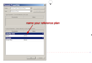
Start a new project. Go to a plan view, then go to the basics tab of the design bar and select ref plane. Draw a horizontal reference plan. Next select the ref plan you just created, right mouse click and go to element properties. In the identity data field for name provide your reference plan with a suitable name. I have called mine ref 1. For those who still have there Autocad head on, think of this as a named UCS. If you now select your reference plane in a view, you will discover that it has a name tagged to it.
Next go to a South elevation. Select the modelling tab from the design bar.
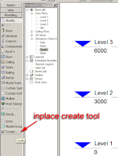
At the bottom of this menu you will see a tool in the shape of a chair labelled create.
Click the create tool, next a dialogue box will appear labelled “family category and parameters”. You will see a list of different modelling categories. The best way to look at this is a form of layering, I know this is not strictly true, but when I am training inplace families, it the easiest way to look at it. If you plan to create a piece of geometry which is going to a wall, select the wall category, if its going to be a structural form, put it in structural framing category and so on.
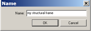 In this example my geometry is going to be a structural frame. Select the ok button. Another dialogue box will appear asking you to provide a name. This has to be unique as it will be the unique identifier in the Revit data base. Provide a suitable name.
Once you select ok, you will notice the design bar has changed, you are now in the inplace family editor.
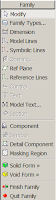
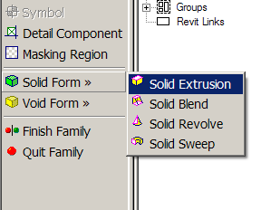
Next select solid form > solid extrusion.
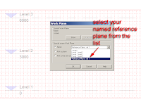
The work plane dialogue box will appear. From the drop down list select your named reference plan, this will become the active work plane, so you will be able to sketch your shape on this work plane.
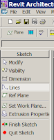
The design bar will change yet again as you are now in the sketch mode which allows you to sketch a closed shape for your extrusion.
 Using the drafting tools, sketch a closed shape for your extrusion. Be mindful that the shape is closed, if it isn’t, rest assured, Revit will warn you! Also watch out for over lapping lines. You will notice in my example that the line work to form the extrusion is completely closed.
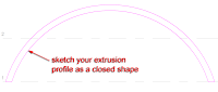
Once you have created your sketch, select finish sketch from the design bar.
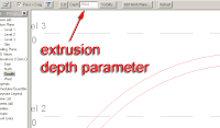
Select the shape you have just created and you will discover the extrusion parameter is now available in the options bar, so you can change the extrusion of the geometry if you require.
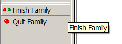
Once you’ve finished tweaking your element, select finish family from the design bar and this will exit your from the family editor.
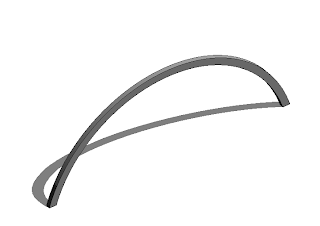
If you now go to a default 3d view, you will see your newly created inplace family!!!
 You now decide that you want a couple of these inplace families in your model. So go to a plan view, select the element and try to either copy or move it!!! Hmmmm that’s strange, I can only move it along the reference plan, that’s not much good.
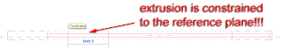
So you swear and you curse at the application saying how much better 3dsmax and Autocad is at modelling and then you remember…… you tied the element to the reference plan, so Revit is only acting on what you told it. So how do you copy the element of move it. Well GROUP it. Then you can copy as much as you like.
So select the element and choose group from the toolbar across the top of the screen.

The create model group dialogue box will appear.
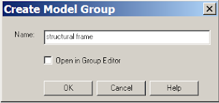
Name the group and then copy away using the copy tool!!!!
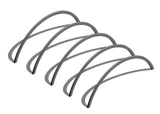
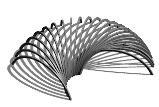
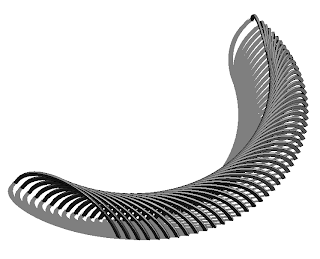
You will discover that the linear array tool will not work, which I don’t understand why that is, but the polar array tool does, strange.
Well I hope that was helpful and enjoy your inplace family modelling.
Well I hope that was helpful and enjoy your inplace family modelling.
3 comments :
You could copy the in-place family you created if you include the reference plane in the selection.
You could make a linear array with your example in-place family if you create a group with the reference plane.
Thankyou,
this have saved me a lot of stress!
Hi David,
I am having a doubt in CAD Export in DWG format.
I have to cross check the following case:
1. Start Export -> CAD Formats - >DWG Files.
2. Select DWG Properties tab.
3. Press ... button.
(Now the Export Layers dialog is opened).
4. Now set the layer "xyz" for Walls -> Finish 1 [4].
5. Press OK button and Proceed the Drawing Export operation.
In The output DWG, I am not able to see the layer xyz.
Please note that I am very new to Revit and My Revit Project contains only Basic Wall Elements.
if possible, Please teach me the constraints at which I can see the XYZ layer with AutoCAD entities.
Post a Comment