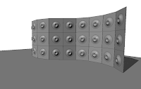
Recently I had a request from one of the clients I work with, who required a bespoke curtain wall system. He wanted to create curtain wall system which was more like a glass rain screen cladding system. The curtain wall would actually be hung off the side of the building, but what the client actually wanted to show was that each panel in the system had a 100mm gap between each panel when viewed in elevation. Therefore it was more decorative rather than a weather proof panel system. This is straight forward to achieve using a custom curtain wall panel family in a curtain wall system. This tutorial will hopefully introduce you to the basics of creating custom curtain wall systems.
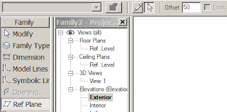
Start Revit; then go to file>new> family and choose Metric Curtain Wall panel.rft (imperial version if you are in the US). This will open up a new default curtain wall panel family in the family editor. If you haven’t done any family editing before, don’t worry, because this exercise will step you through everything you require.
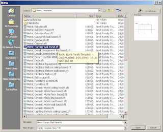
Family templates are hardwired templates for different elements within Revit. Families are the back bone of Revit, if you are going to create a new door family, you pick the door template. If you want to create a window family, then pick a window template and so on. Autodesk have included a number of pre-set parameters in each template to help you along. However, I digress, returning to our new curtain wall panel family, go to an Exterior elevation.
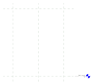
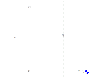
You will notice 4 reference planes, to horizontal, two vertical. These are the bones of the family. If you where to build a panel in the normal fashion the geometry would need to be locked to these reference panels. However our system needs a 100mm gap between adjacent panels. So go to Ref plane tool in the design bar, then using the pick tool set an offset of 50mm and create 4 additional ref planes placed on the inner side of the main reference planes in the family. You should end up with something like this……
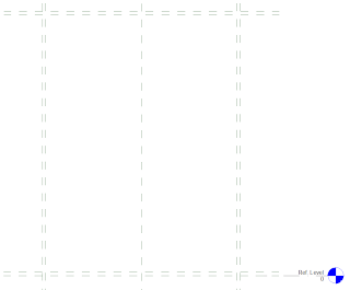
Next using the linear dimension tool, create a dimension between the main reference plan and the reference plan you have just created.
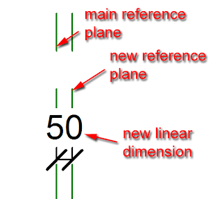
You should end up with this….
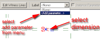
Next select one of the dimensions. When you select the dimension the label tool will appear in the options bar. Select the drop down menu which appears and then select Add parameter.
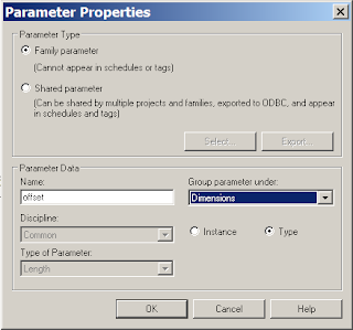
The Parameter properties dialogue box will appear. Give your new parameter a suitable name, I have called mine “offset”. Group the parameter under “dimensions” and set the parameter as a type parameter. Then select the OK button.
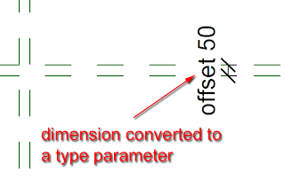
The dimension will now convert to a parameter and will display like this.
 Next we will now flex the parameter to see if it is working correctly. In the design bar select “family type”.
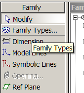 This will open up the family type dialogue box. Locate the parameter you have just assigned and changing the parameter dimension from 50mm to 100mm and click “apply”, this will flex the dimension. Assuming everything is working correctly, return the parameter to 50mm and exit out of the dialogue box.
Next select the other 3 dimensions and assign the offset parameter to each dimension. To do this, select the dimension and select “offset” from the label drop down menu in the options bar.
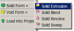
Now we have created the bones of the curtain wall panel, we will now model the actual glass panel. From the design bar go to solid form > solid extrusion.
 The design bar will change to sketch mode for the extrusion. From the options bar, set the extrusion depth to 35mm for the thickness for the glass.
  Now use the pick line tool to place lines for the extrusion on the reference lines you created earlier. However, as you place each line, a pad lock will appear, make sure you lock the pad lock. This will lock the extrusion line to the reference plane.
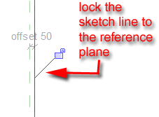 Continue placing reference lines until you have something like this.
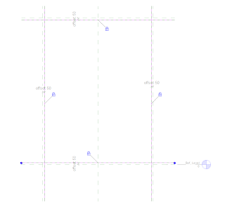 Now use the trim tool to trim the sketch lines until you have a nice clear rectangle.
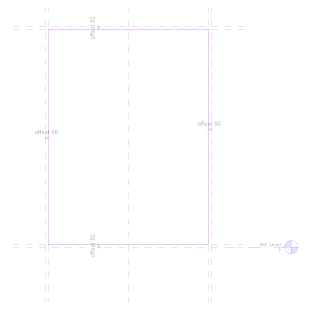 Now select finish sketch from the design bar. Go to the default 3d view icon, to view you panel in 3d.
Select the panel, right mouse click and from the contextual menu select element properties.
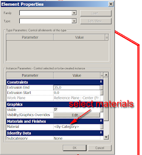
The element properties dialogue box will appear. Next select materials, the materials dialogue box will appear, select glass material, click the “apply” button and “ok” out of the dialogue box.
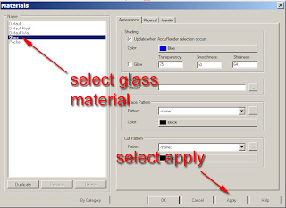
Your 3d panel will now have a glass material applied to it.
We will now save our panel to a suitable location on the hard drive.
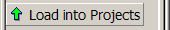
Assuming you started Revit from scratch, you should have a project already started and running in the background. If this is the case, you can load your new panel directly into the project by clicking “load into projects”.
 Revit should switch you over to your project.
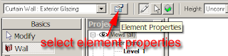
Now select walls and Curtain wall: exterior glazing (if you are using the metric template). Before drawing a piece of curtain wall, go to the element properties for the curtain wall.
 Click edit/new from the dialogue box.
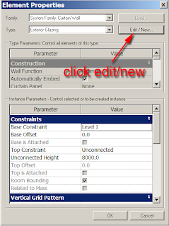
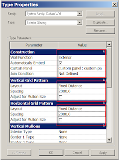
In the Type properties set the following values.
Construction
Make the curtain panel:- custom panel ( your new panel you have just created)
Vertical Grid Pattern
Layout:-Fixed Distance
Spacing:- 2000mm (6’ 6”)
Horizontal Grid Pattern
Layout:-Fixed Distance
Spacing:- 2000mm (6’ 6”)
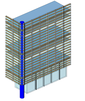
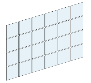
Select apply and exit out of the dialogue boxes. You are now ready to draw your new curtain wall with the panel embedded into it. Draw the wall in the normal fashion. You may get an error if Revit can’t actually form a panel depending on the length of the curtain wall you are drawing. If you have followed my guidelines correctly and you draw your wall 12m long, then the 2m panel will fit in without any issues.
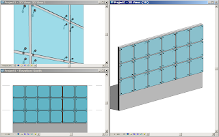
It’s worth going back to the type properties and playing with the figures as well as Layout conditions to set the different results that can be achieved. If you want to see a movie of the above example, select this link. I hope you find this is helpful. I will introduce some more advanced tricks and tips for Curtain Walls in future postings, but this should be enough to get your juices flowing.
14 comments :
Thanks for this. I definitly appreciate the hard work put into this kind of thing. Thanks
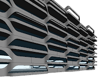
looking forward to a post on that 3rd curtainwall sample type
some really cool concepts on here, looking forward to trying some of them out myself. However,Is there a way to use curtain wall on the horizontal plane instead of the vertical one??
again, many thanks for a great post..
Thanks for the kind comments. You can create horizontal curtain walling by doing the following. Create a flat roof, then go to its properties and change the family from "System family:Basic Roof" to "System Family:Sloped Glazing". You will see that the roof then changes to the same type of curtain system used in CW's. You will be able to nest in panels exactly like you can on a CW system.I hope this helps.
Was trying to do a special deck so after converting the flat roof to a sloped glazing and loaded my curtain panel got the following message..
Loaded family curtain panels cannot be used in non-rectangular cells of the curtain host. Type-driven panels from non-rectangular cells were unlocked and left unchanged. ??????
This was a great help. Thanks. The trouble I'm having is in rendering custom solid panels after they have been created. I want to create a variety of metal panels, but they all render the same flat gray when i've loaded them in Revit 09. Thoughts?
thank you very much, now I understand how to do it.
David, awesome tutorial. do you know how to do a continuous corner panel with something like a curtain wall? meaning a metal panel that bends around a 90 degree corner.
hi im trying to make a CW and create something like the start screen on RAC2011, so i made my custom CW by extrusion, then i load my pattern (made in ACAD) and use it to generate Voids, it looks greate but it only seems to work on rectangular panels, can i make it work like the system courtain walls, so that when i edit the profile of the wall it automaticly change. i get an error every time i do that, and revit prompts me to delete the panel then replace it.
Hey just wanted to say thanks for this awesome tutorial!
I really appreciate of your work. Because you have made excellent post. It has been helping for me.
Rain screen cladding
In your last photo it appears that the glazing is attached to the outside of the mullions. How do you acheive that?
In your last photo it appears that the glazing is attached to the outside of the mullions. How do you acheive that?
With this kind of information all you need is quotes for your double glazed windows. Which I can provide :)
Post a Comment