Not to be out done by the architectural team, the structural boys also have a new build posted (20070810_1700). This includes the following inprovements:-
• Straight beam joins and cuts back properly when supported by vertical curved beams.
• Improves stability after receiving a corrupt element warning when opening a project.
• Improves stability when saving a Project with a linked DWG™ file that contains an image.
• Improves stability when applying a view template to a sheet view.
• In Windows Vista™ operating system, allows the ability to write to revit.ini, licpath.lic,
KeyboardShortcuts.txt, and the Journals folder.
• Line based families contained in a group are no longer flipped when the group is mirrored.
• Improves stability when importing group into Titleblock family.
• Allows the ability to export renderings to TIFF format.
• When temporary dimension text too small to read, user can adjust the size of the font through Revit.ini.
• Linked DWG added by another user will now show up in Manage Links after reload latest.
• “Relative” spot elevation updates automatically with the change in Level elevation.
• When exporting to DWG file, overlapping lines that share a point are no longer missing in the resulting
DWG.
The build can be downloaded from:-
http://usa.autodesk.com/adsk/servlet/index?siteID=123112&id=9262026
Wednesday, August 22, 2007
New Build of Revit Architecture 2008 is released
Autodesk have today released a new build of Revit Architecture, SP2 build (20070810_1700). It includes the following fixes and minor improvements.
• Improves stability after receiving a corrupt element warning when opening a project.
• Publish to DWF™ functions when Rooms are present and are clipped by the viewport.
• Improves stability when saving a Project with a linked DWG™ file that contains an image.
• Improves stability when applying a view template to a sheet view.
• In Windows Vista™ operating system, allows the ability to write to revit.ini, licpath.lic,
KeyboardShortcuts.txt, and the Journals folder.
• Line based families contained in a group are no longer flipped when the group is mirrored.
• Improves stability when importing group into Titleblock family.
• Allows the ability to export renderings to TIFF format.
• When temporary dimension text too small to read, user can adjust the size of the font through Revit.ini.
• Linked DWG added by another user will now show up in Manage Links after reload latest.
• “Relative” spot elevation updates automatically with the change in Level elevation.
• When exporting to DWG, overlapping lines that share a point are no longer missing in the resulting DWG
file.
The build can be downloaded from:-
http://usa.autodesk.com/adsk/servlet/index?siteID=123112&id=9262388
Monday, August 20, 2007
Custom Curtain Wall Panels
Autodesk Revit's Curtain Walls on the face of it, look reasonably basic, but with a bit of lateral thinking you can create extremely complex systems. 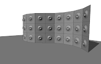
Recently I had a request from one of the clients I work with, who required a bespoke curtain wall system. He wanted to create curtain wall system which was more like a glass rain screen cladding system. The curtain wall would actually be hung off the side of the building, but what the client actually wanted to show was that each panel in the system had a 100mm gap between each panel when viewed in elevation. Therefore it was more decorative rather than a weather proof panel system. This is straight forward to achieve using a custom curtain wall panel family in a curtain wall system. This tutorial will hopefully introduce you to the basics of creating custom curtain wall systems.
Start Revit; then go to file>new> family and choose Metric Curtain Wall panel.rft (imperial version if you are in the US). This will open up a new default curtain wall panel family in the family editor. If you haven’t done any family editing before, don’t worry, because this exercise will step you through everything you require.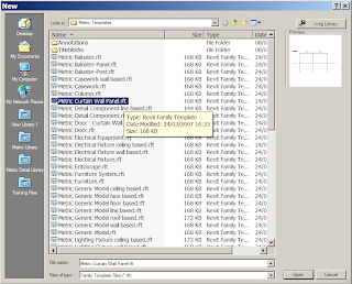
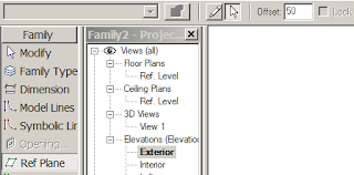
Family templates are hardwired templates for different elements within Revit. Families are the back bone of Revit, if you are going to create a new door family, you pick the door template. If you want to create a window family, then pick a window template and so on. Autodesk have included a number of pre-set parameters in each template to help you along. However, I digress, returning to our new curtain wall panel family, go to an Exterior elevation.
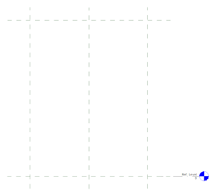
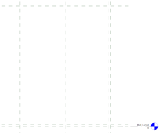
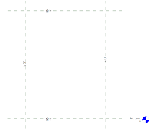
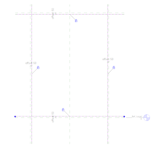
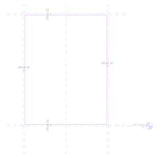
You will notice 4 reference planes, to horizontal, two vertical. These are the bones of the family. If you where to build a panel in the normal fashion the geometry would need to be locked to these reference panels. However our system needs a 100mm gap between adjacent panels. So go to Ref plane tool in the design bar, then using the pick tool set an offset of 50mm and create 4 additional ref planes placed on the inner side of the main reference planes in the family. You should end up with something like this……
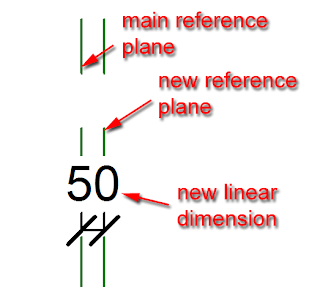
Next using the linear dimension tool, create a dimension between the main reference plan and the reference plan you have just created.
You should end up with this….
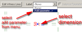
Next select one of the dimensions. When you select the dimension the label tool will appear in the options bar. Select the drop down menu which appears and then select Add parameter.
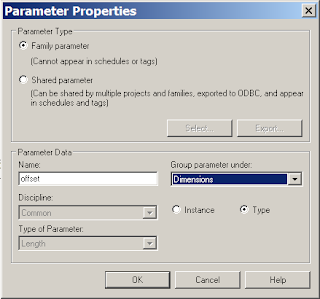
The Parameter properties dialogue box will appear. Give your new parameter a suitable name, I have called mine “offset”. Group the parameter under “dimensions” and set the parameter as a type parameter. Then select the OK button.
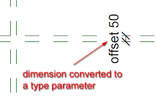
The dimension will now convert to a parameter and will display like this.
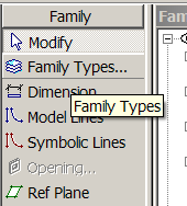
 Next we will now flex the parameter to see if it is working correctly. In the design bar select “family type”.
 This will open up the family type dialogue box. Locate the parameter you have just assigned and changing the parameter dimension from 50mm to 100mm and click “apply”, this will flex the dimension. Assuming everything is working correctly, return the parameter to 50mm and exit out of the dialogue box.
Next select the other 3 dimensions and assign the offset parameter to each dimension. To do this, select the dimension and select “offset” from the label drop down menu in the options bar.
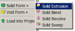
Now we have created the bones of the curtain wall panel, we will now model the actual glass panel. From the design bar go to solid form > solid extrusion.
 The design bar will change to sketch mode for the extrusion. From the options bar, set the extrusion depth to 35mm for the thickness for the glass.
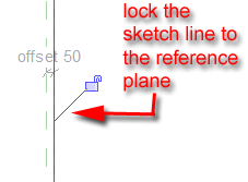
  Now use the pick line tool to place lines for the extrusion on the reference lines you created earlier. However, as you place each line, a pad lock will appear, make sure you lock the pad lock. This will lock the extrusion line to the reference plane.
 Continue placing reference lines until you have something like this.
 Now use the trim tool to trim the sketch lines until you have a nice clear rectangle.
 Now select finish sketch from the design bar. Go to the default 3d view icon, to view you panel in 3d.
Select the panel, right mouse click and from the contextual menu select element properties.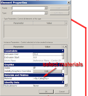
The element properties dialogue box will appear. Next select materials, the materials dialogue box will appear, select glass material, click the “apply” button and “ok” out of the dialogue box.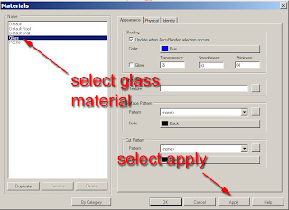
Your 3d panel will now have a glass material applied to it.
We will now save our panel to a suitable location on the hard drive.
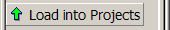
Assuming you started Revit from scratch, you should have a project already started and running in the background. If this is the case, you can load your new panel directly into the project by clicking “load into projects”.
 Revit should switch you over to your project.
Now select walls and Curtain wall: exterior glazing (if you are using the metric template). Before drawing a piece of curtain wall, go to the element properties for the curtain wall.
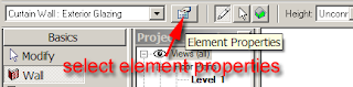 Click edit/new from the dialogue box.
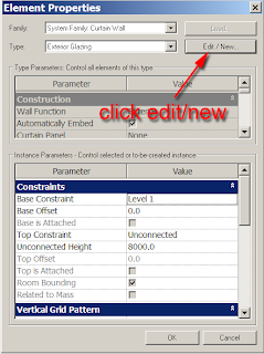
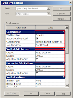
In the Type properties set the following values.
Construction
Make the curtain panel:- custom panel ( your new panel you have just created)
Vertical Grid Pattern
Layout:-Fixed Distance
Spacing:- 2000mm (6’ 6”)
Horizontal Grid Pattern
Layout:-Fixed Distance
Spacing:- 2000mm (6’ 6”)
Select apply and exit out of the dialogue boxes. You are now ready to draw your new curtain wall with the panel embedded into it. Draw the wall in the normal fashion. You may get an error if Revit can’t actually form a panel depending on the length of the curtain wall you are drawing. If you have followed my guidelines correctly and you draw your wall 12m long, then the 2m panel will fit in without any issues.
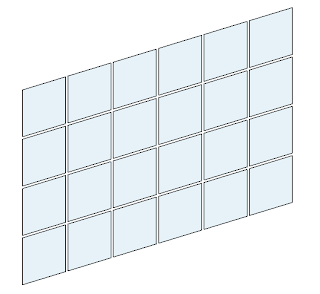
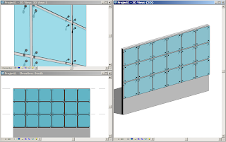
It’s worth going back to the type properties and playing with the figures as well as Layout conditions to set the different results that can be achieved. If you want to see a movie of the above example, select this link. I hope you find this is helpful. I will introduce some more advanced tricks and tips for Curtain Walls in future postings, but this should be enough to get your juices flowing.
Recently I had a request from one of the clients I work with, who required a bespoke curtain wall system. He wanted to create curtain wall system which was more like a glass rain screen cladding system. The curtain wall would actually be hung off the side of the building, but what the client actually wanted to show was that each panel in the system had a 100mm gap between each panel when viewed in elevation. Therefore it was more decorative rather than a weather proof panel system. This is straight forward to achieve using a custom curtain wall panel family in a curtain wall system. This tutorial will hopefully introduce you to the basics of creating custom curtain wall systems.
Start Revit; then go to file>new> family and choose Metric Curtain Wall panel.rft (imperial version if you are in the US). This will open up a new default curtain wall panel family in the family editor. If you haven’t done any family editing before, don’t worry, because this exercise will step you through everything you require.
Family templates are hardwired templates for different elements within Revit. Families are the back bone of Revit, if you are going to create a new door family, you pick the door template. If you want to create a window family, then pick a window template and so on. Autodesk have included a number of pre-set parameters in each template to help you along. However, I digress, returning to our new curtain wall panel family, go to an Exterior elevation.
You will notice 4 reference planes, to horizontal, two vertical. These are the bones of the family. If you where to build a panel in the normal fashion the geometry would need to be locked to these reference panels. However our system needs a 100mm gap between adjacent panels. So go to Ref plane tool in the design bar, then using the pick tool set an offset of 50mm and create 4 additional ref planes placed on the inner side of the main reference planes in the family. You should end up with something like this……
Next using the linear dimension tool, create a dimension between the main reference plan and the reference plan you have just created.
You should end up with this….
Next select one of the dimensions. When you select the dimension the label tool will appear in the options bar. Select the drop down menu which appears and then select Add parameter.
The Parameter properties dialogue box will appear. Give your new parameter a suitable name, I have called mine “offset”. Group the parameter under “dimensions” and set the parameter as a type parameter. Then select the OK button.
The dimension will now convert to a parameter and will display like this.
Next we will now flex the parameter to see if it is working correctly. In the design bar select “family type”. This will open up the family type dialogue box. Locate the parameter you have just assigned and changing the parameter dimension from 50mm to 100mm and click “apply”, this will flex the dimension. Assuming everything is working correctly, return the parameter to 50mm and exit out of the dialogue box.Next select the other 3 dimensions and assign the offset parameter to each dimension. To do this, select the dimension and select “offset” from the label drop down menu in the options bar.
Now we have created the bones of the curtain wall panel, we will now model the actual glass panel. From the design bar go to solid form > solid extrusion.
The design bar will change to sketch mode for the extrusion. From the options bar, set the extrusion depth to 35mm for the thickness for the glass. Now use the pick line tool to place lines for the extrusion on the reference lines you created earlier. However, as you place each line, a pad lock will appear, make sure you lock the pad lock. This will lock the extrusion line to the reference plane. Continue placing reference lines until you have something like this.Now use the trim tool to trim the sketch lines until you have a nice clear rectangle.Now select finish sketch from the design bar. Go to the default 3d view icon, to view you panel in 3d.Select the panel, right mouse click and from the contextual menu select element properties.
The element properties dialogue box will appear. Next select materials, the materials dialogue box will appear, select glass material, click the “apply” button and “ok” out of the dialogue box.
Your 3d panel will now have a glass material applied to it.
We will now save our panel to a suitable location on the hard drive.
Assuming you started Revit from scratch, you should have a project already started and running in the background. If this is the case, you can load your new panel directly into the project by clicking “load into projects”.
Revit should switch you over to your project.Now select walls and Curtain wall: exterior glazing (if you are using the metric template). Before drawing a piece of curtain wall, go to the element properties for the curtain wall.
Click edit/new from the dialogue box. In the Type properties set the following values.
Construction
Make the curtain panel:- custom panel ( your new panel you have just created)
Vertical Grid Pattern
Layout:-Fixed Distance
Spacing:- 2000mm (6’ 6”)
Horizontal Grid Pattern
Layout:-Fixed Distance
Spacing:- 2000mm (6’ 6”)
Select apply and exit out of the dialogue boxes. You are now ready to draw your new curtain wall with the panel embedded into it. Draw the wall in the normal fashion. You may get an error if Revit can’t actually form a panel depending on the length of the curtain wall you are drawing. If you have followed my guidelines correctly and you draw your wall 12m long, then the 2m panel will fit in without any issues.
It’s worth going back to the type properties and playing with the figures as well as Layout conditions to set the different results that can be achieved. If you want to see a movie of the above example, select this link. I hope you find this is helpful. I will introduce some more advanced tricks and tips for Curtain Walls in future postings, but this should be enough to get your juices flowing.
Thursday, August 16, 2007
Mullions as Louvers
I wanted to share this little bit of modelling wisdom with you. I can’t take credit for this as it was a technique shown to me by Kevin Parks at HOK, who I believe originally, picked it from legendary Revit guru Phil Read.
Recently HOK had a requirement to create a external louvered system for the facade of a building. However, the challenge for this was that the facade was sloped as well as curved in plan.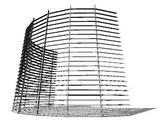 So what this is how it was achieved……
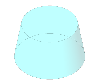
First create a mass element as a blend; which blends from circle into another circle. If you are not sure about using massing refer to Ian’s tutorial on his excellent Revit Zone website. Make the blend a reasonable size, in this instance the bottom radius was 10m, top radius was 7m, height was 12m.

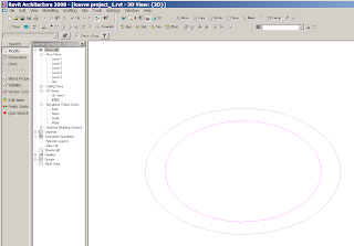
When you finish your mass blend you should have something which looks like this.
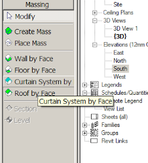
 Then using the curtain system by face in the massing tools, we will skin the mass with a curtain wall system. However, before we do this we are going to create a new curtain wall type, which includes some specific settings as well as mullions to define the louvers. You will need to take care when doing this as it can create a rather heavy model, so play this technique before unleashing it on any live projects!!!
Pick the curtain system by face tool, go to the options bar and then element properties.
Next click duplicate, this will duplicate the existing curtain wall style, you also have a chance to rename it.
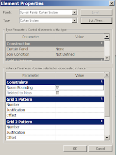
Now we are going to make to some changes to this particular curtain wall style in its type properties. You may want to follow my settings so that you can achieve similar results.
In the construction set the Curtain Panel to be “Empty System Panel-Empty”
Set Grid Pattern 1 to Layout fixed distance, spacing 1000mm.
Set Grid Pattern 2 to Layout fixed distance, spacing 200mm. Make sure adjust for mullion size is ticked.
Leave Grid 1 Mullion empty.
In Grid 2 Mullion, make sure you select a suitable mullion for Interior type. Use one of the default ones for this exercise, but you could create your own profile and assign this to a suitable mullion style.


Once you have setup these different parameters, select ok to come out of the type properties and then the element properties dialogue box.
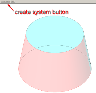
Now using your newly created curtain wall style, use the curtain system by face tool and select the blend shape we create in the first place. Select one half of the blend arc, so that it goes red. Then click the create system button which will appear in the options bar.
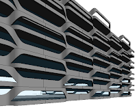
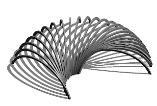
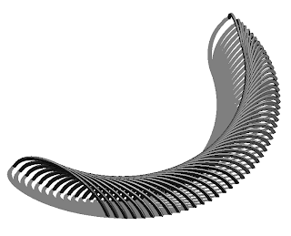
Now after some heavy calculation!!! Revit will generate the curtain wall system.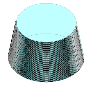 All it requires you to do now is, hide your mass and set up a nice perspective view, turn shadows on and to show off your handy work!!!
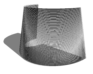
Recently HOK had a requirement to create a external louvered system for the facade of a building. However, the challenge for this was that the facade was sloped as well as curved in plan.
So what this is how it was achieved……First create a mass element as a blend; which blends from circle into another circle. If you are not sure about using massing refer to Ian’s tutorial on his excellent Revit Zone website. Make the blend a reasonable size, in this instance the bottom radius was 10m, top radius was 7m, height was 12m.
When you finish your mass blend you should have something which looks like this.
Then using the curtain system by face in the massing tools, we will skin the mass with a curtain wall system. However, before we do this we are going to create a new curtain wall type, which includes some specific settings as well as mullions to define the louvers. You will need to take care when doing this as it can create a rather heavy model, so play this technique before unleashing it on any live projects!!!Pick the curtain system by face tool, go to the options bar and then element properties.
The element properties dialogue box will now appear. We are now going to duplicate one of the standard shipping curtain wall styles and rename it. So in element properties, click the edit/new button.
Next click duplicate, this will duplicate the existing curtain wall style, you also have a chance to rename it.
Now we are going to make to some changes to this particular curtain wall style in its type properties. You may want to follow my settings so that you can achieve similar results.
In the construction set the Curtain Panel to be “Empty System Panel-Empty”
Set Grid Pattern 1 to Layout fixed distance, spacing 1000mm.
Set Grid Pattern 2 to Layout fixed distance, spacing 200mm. Make sure adjust for mullion size is ticked.
Leave Grid 1 Mullion empty.
In Grid 2 Mullion, make sure you select a suitable mullion for Interior type. Use one of the default ones for this exercise, but you could create your own profile and assign this to a suitable mullion style.
Once you have setup these different parameters, select ok to come out of the type properties and then the element properties dialogue box.
Now using your newly created curtain wall style, use the curtain system by face tool and select the blend shape we create in the first place. Select one half of the blend arc, so that it goes red. Then click the create system button which will appear in the options bar.
Now after some heavy calculation!!! Revit will generate the curtain wall system.
All it requires you to do now is, hide your mass and set up a nice perspective view, turn shadows on and to show off your handy work!!!The end result may not make it into your next architectural project, but it does show the power of Revit if you think out side of the box. :-)
Wednesday, August 15, 2007
You’ve tied me to a reference plan and now I can’t move?????!!!!
You’ve got into inplace families and discovered that you can create allsorts of funky geometry within your project without to having even to jump into the scary “family editor”! However, you create your lovely piece of geometry, followed the rules just like your trainer told you, but then you find you can’t move or copy the geometry you created!! Hmmmmmmmm
Inplace families are excellent for one off pieces of geometry for your project. They can also be extremely useful at scheme design stage when you what to create some geometry but you don’t need the overhead of creating the element using a family template and the family editor. Inplace families can have an overhead on your project if they contain too many voids and cuts, so you will need to watch this.
So let’s look at the issue.
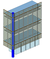
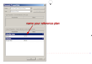
Start a new project. Go to a plan view, then go to the basics tab of the design bar and select ref plane. Draw a horizontal reference plan. Next select the ref plan you just created, right mouse click and go to element properties. In the identity data field for name provide your reference plan with a suitable name. I have called mine ref 1. For those who still have there Autocad head on, think of this as a named UCS. If you now select your reference plane in a view, you will discover that it has a name tagged to it.
Next go to a South elevation. Select the modelling tab from the design bar.
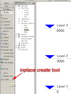
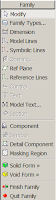
At the bottom of this menu you will see a tool in the shape of a chair labelled create.
Click the create tool, next a dialogue box will appear labelled “family category and parameters”. You will see a list of different modelling categories. The best way to look at this is a form of layering, I know this is not strictly true, but when I am training inplace families, it the easiest way to look at it. If you plan to create a piece of geometry which is going to a wall, select the wall category, if its going to be a structural form, put it in structural framing category and so on.
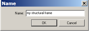 In this example my geometry is going to be a structural frame. Select the ok button. Another dialogue box will appear asking you to provide a name. This has to be unique as it will be the unique identifier in the Revit data base. Provide a suitable name.
Once you select ok, you will notice the design bar has changed, you are now in the inplace family editor.
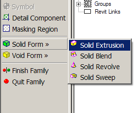
Next select solid form > solid extrusion.
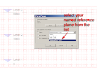
The work plane dialogue box will appear. From the drop down list select your named reference plan, this will become the active work plane, so you will be able to sketch your shape on this work plane.
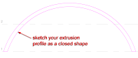
The design bar will change yet again as you are now in the sketch mode which allows you to sketch a closed shape for your extrusion.
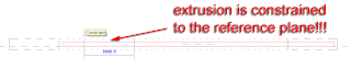
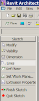 Using the drafting tools, sketch a closed shape for your extrusion. Be mindful that the shape is closed, if it isn’t, rest assured, Revit will warn you! Also watch out for over lapping lines. You will notice in my example that the line work to form the extrusion is completely closed.
Once you have created your sketch, select finish sketch from the design bar.
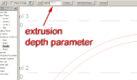
Select the shape you have just created and you will discover the extrusion parameter is now available in the options bar, so you can change the extrusion of the geometry if you require.
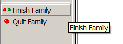
Once you’ve finished tweaking your element, select finish family from the design bar and this will exit your from the family editor.
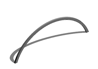
If you now go to a default 3d view, you will see your newly created inplace family!!!
 You now decide that you want a couple of these inplace families in your model. So go to a plan view, select the element and try to either copy or move it!!! Hmmmm that’s strange, I can only move it along the reference plan, that’s not much good.
So you swear and you curse at the application saying how much better 3dsmax and Autocad is at modelling and then you remember…… you tied the element to the reference plan, so Revit is only acting on what you told it. So how do you copy the element of move it. Well GROUP it. Then you can copy as much as you like.
So select the element and choose group from the toolbar across the top of the screen.
Name the group and then copy away using the copy tool!!!!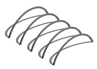
Inplace families are excellent for one off pieces of geometry for your project. They can also be extremely useful at scheme design stage when you what to create some geometry but you don’t need the overhead of creating the element using a family template and the family editor. Inplace families can have an overhead on your project if they contain too many voids and cuts, so you will need to watch this.
So let’s look at the issue.
Start a new project. Go to a plan view, then go to the basics tab of the design bar and select ref plane. Draw a horizontal reference plan. Next select the ref plan you just created, right mouse click and go to element properties. In the identity data field for name provide your reference plan with a suitable name. I have called mine ref 1. For those who still have there Autocad head on, think of this as a named UCS. If you now select your reference plane in a view, you will discover that it has a name tagged to it.
Next go to a South elevation. Select the modelling tab from the design bar.
At the bottom of this menu you will see a tool in the shape of a chair labelled create.
Click the create tool, next a dialogue box will appear labelled “family category and parameters”. You will see a list of different modelling categories. The best way to look at this is a form of layering, I know this is not strictly true, but when I am training inplace families, it the easiest way to look at it. If you plan to create a piece of geometry which is going to a wall, select the wall category, if its going to be a structural form, put it in structural framing category and so on.
In this example my geometry is going to be a structural frame. Select the ok button. Another dialogue box will appear asking you to provide a name. This has to be unique as it will be the unique identifier in the Revit data base. Provide a suitable name.Once you select ok, you will notice the design bar has changed, you are now in the inplace family editor.
Next select solid form > solid extrusion.
The work plane dialogue box will appear. From the drop down list select your named reference plan, this will become the active work plane, so you will be able to sketch your shape on this work plane.
The design bar will change yet again as you are now in the sketch mode which allows you to sketch a closed shape for your extrusion.
Using the drafting tools, sketch a closed shape for your extrusion. Be mindful that the shape is closed, if it isn’t, rest assured, Revit will warn you! Also watch out for over lapping lines. You will notice in my example that the line work to form the extrusion is completely closed.Once you have created your sketch, select finish sketch from the design bar.
Select the shape you have just created and you will discover the extrusion parameter is now available in the options bar, so you can change the extrusion of the geometry if you require.
Once you’ve finished tweaking your element, select finish family from the design bar and this will exit your from the family editor.
If you now go to a default 3d view, you will see your newly created inplace family!!!
You now decide that you want a couple of these inplace families in your model. So go to a plan view, select the element and try to either copy or move it!!! Hmmmm that’s strange, I can only move it along the reference plan, that’s not much good.So you swear and you curse at the application saying how much better 3dsmax and Autocad is at modelling and then you remember…… you tied the element to the reference plan, so Revit is only acting on what you told it. So how do you copy the element of move it. Well GROUP it. Then you can copy as much as you like.
So select the element and choose group from the toolbar across the top of the screen.

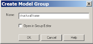
The create model group dialogue box will appear.
Name the group and then copy away using the copy tool!!!!
You will discover that the linear array tool will not work, which I don’t understand why that is, but the polar array tool does, strange.
Well I hope that was helpful and enjoy your inplace family modelling.
Well I hope that was helpful and enjoy your inplace family modelling.
Subscribe to:
Posts
(
Atom
)