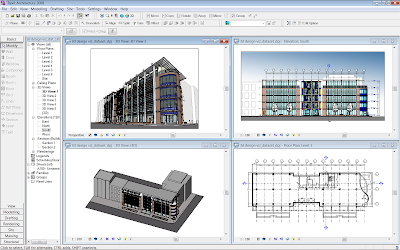
The headliner for Revit Architecture 2009 is the replacement of the aging Accurender engine with Mental Ray. This will definitely improve the overall quality of your renders compared with Accurender. Remember, Mental Ray is the same rendering engine which resides in 3dsmax and across the whole of the Autodesk product portfolio; so you can rest assured the quality will be high.
When you are in a 3d view or perspective, you will notice an additional tool in the view control bar. The new teapot icon allows you to quickly access the render dialogue box. Alternatively, you can still access the render tools from the design bar or pull down menu.

The new layout of the render dialogue is excellent, it’s simple to use and understand. Somebody at Autodesk has really listened to what the architect and designers requires when it comes to rendering images.

Revit Architecture 2009 also includes render preset such as draft, low, medium, high and best allowing you to get quick results. However, you also have the ability to drill down and create your own custom setup for a particular view if you want too. In general, increasing (or turning on) any one of these settings increases the quality of the rendered image. Increasing these values or multiple settings may increase render time exponentially, so you’ve been warned!! But on a positive note, if you have a dual core or quad core processor in your workstation or laptop, then the Mental Ray render will make use of these extra cores. One thing I did find was that there was no way I could transfer custom setting between views, which is a shame. I am sure someone will enlighten me if I have got it wrong.

All lighting fixtures are now photometric and will use an IES file to define lighting parameters. If you open an existing light fitting family you will notice that you have the ability to specify the IES file for the light fitting. Revit Architecture 2009 uses this information from the IES file to define the geometric shape of the light source.
The materials provided within Revit Architecture 2009 have been reassigned Mental Ray material properties. These materials are far more realistic and are stored as part of the project file. If you go to the materials dialogue box, settings pull down menu>materials, you will notice that this dialogue box has been overhauled. The render appearance tab allows you to control the settings for the material you want to define. Revit includes a library of standard materials, but you can also define your own custom materials if you want.
Material appearance :-

Library view:-

Revit Architecture 2009 has also simplified the process for creating different lighting conditions. You will find preset for the following conditions:-
Exterior : Sun only
Exterior : Sun and Artificial
Exterior : Artificial only
Interior : Sun only
Interior : Sun and Artificial
Interior : Artificial only
So to test these I produced a very simple scene which you can see below. I then render the scene a number of times using some of these presets.
 Exterior - sun only
  Exterior - artificial + sun
 Interior - only
  Interior - sun + artificial
  Interior - sun only
Overall, I am very impressed with the new rendering engine. I am positive that new and existing users will get to grips with this tool and its settings very quickly and I am expecting to see some excellent images from the Revit community in the not too distant future.


 When you want to close the loop of wall, just right mouse click to invoke the Osnap override command.


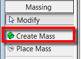 Click create new mass.
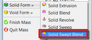
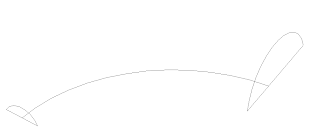
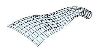
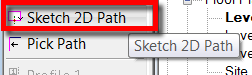 If you now open a 3d view, you will see the path you have just drawn with two green crosses at either end of the path. These are the two planes where we will draw our profiles.
 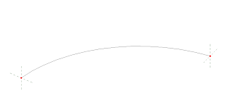 So select Sketch profile 1 from the design bar and use the drafting tools to sketch a closed shape for our first profile. Once this profile is finished, do the same exercise for Sketch profile 2.
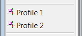
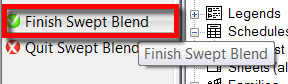
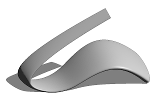
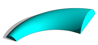 The new Swept Blend tool will allow you to create geometry like this…..
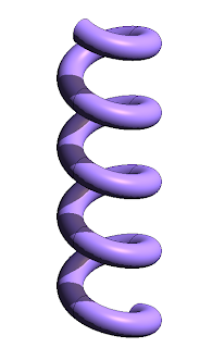
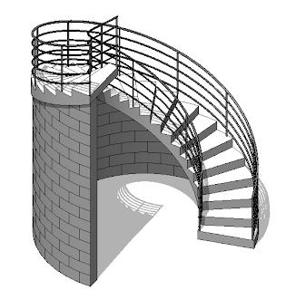
 Another challenge in the past was to create a spiral piece of wall to infill under a spiral ramp or staircase. Click on the image below to open a movie example....